Mapping
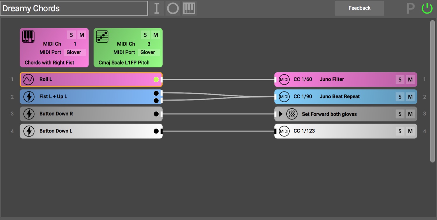
Mapping is the primary purpose of Glover. It is a creative process, where you can design your gestures + movements, and choose which musical (or other) outputs they will control. In their most basic form, mappings are connections from inputs to outputs. They give you an opportunity to create your own instruments.
Contents
Mapping Inputs
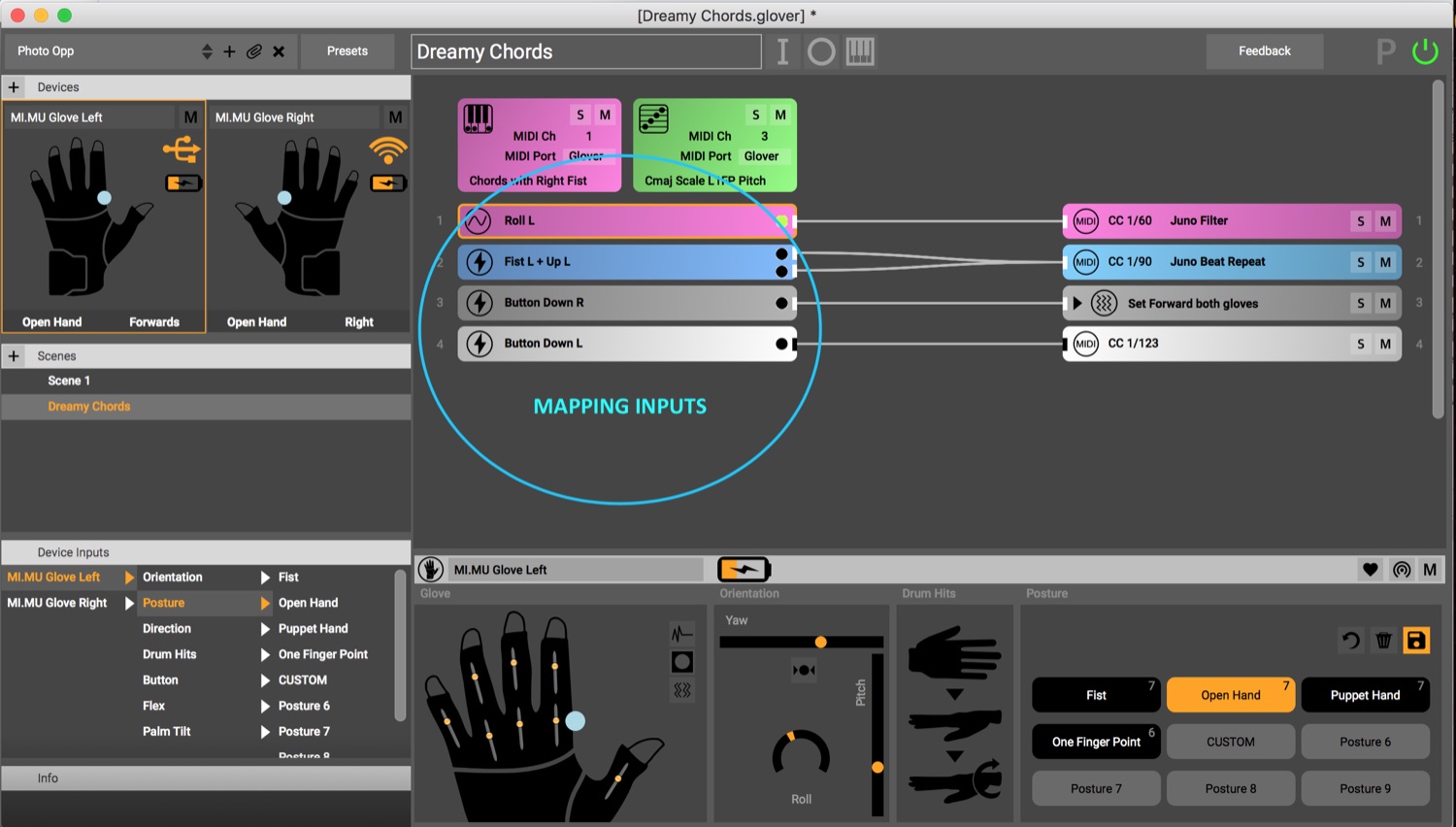
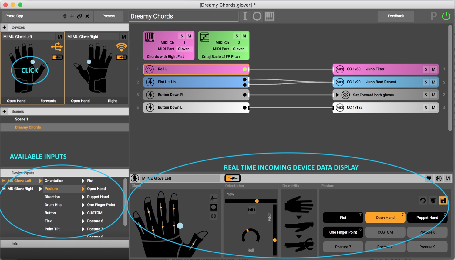
The inputs available to you for a glove or other device can be seen by clicking on that device in the Device Pane of Glover. The available inputs are listed in nested menus in the lower left pane, with real-time inputs visible in the device input pane across the bottom of the screen. Depending on the type of device, its sensors and machine learning algorithms can provide different types of inputs.
Input Types
Glover provides various options for control within each general type of input. A new input is created by clicking on the “I” button at the top of the screen and dragging one of the listed device inputs into the empty “Inputs” panel. An existing input can be edited by clicking on that input in the main Glover mapping pane. Input options appear in the inspector pane at the bottom of the window and are automatically adjusted when new inputs are added. Logically conflicting inputs, such as making two postures or pointing left and right at the same time, are automatically disallowed by Glover. In the top right corner of the Inputs panel you see the colours of the input types that are allowed. You can make input combinations across multiple devices. One Mapping Input can for example use a qualifier from Gliss and a movement from a Leap Motion,All options that Glover can send out for the combination of movements and events in the input box are then shown in the right pane of the inspector window.
- Movements Movement inputs are descriptions of motion that can be thought of as giving continuous, moment-by-moment answers to questions like “Where is my arm pointing?” or “How much is my index finger bent right now?”
- Events Event inputs are discrete inputs that can act as “states” or “events,” which generally can be thought of as able to answer a yes or no question, such as “Is my arm pointed up?” or “Am I making a fist?” These types of inputs are useful as triggers or as ways of distinguishing movements from each other. Qualifiers like postures or diretions and Events like Drumhits can both be Events.
Movements
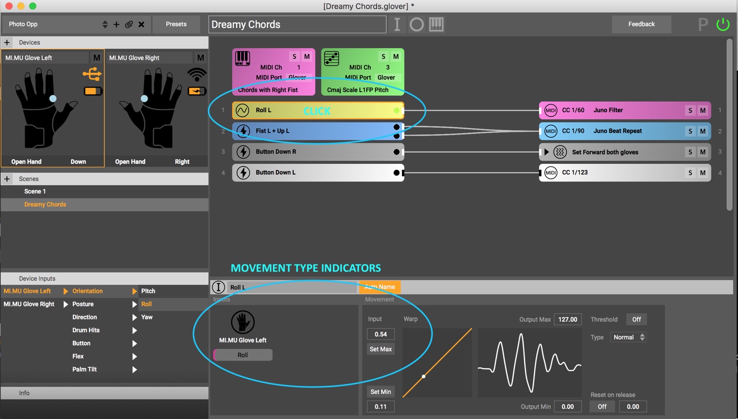
Individual movement inputs indicated by a pink color in the input box. The available options for controlling information about movements that can be sent out via MIDI or OSC (see the Output Mappings section for guidance on how to select appropriate output messages) are:
- Input range [min] and [max] This is the range of motion you would like to use. Set this range of motion by performing the motion you are interested in mapping and looking at the real-time data that is displayed by Glover. You can see how the movement goes up and down. Make the gesture in the position you would like to be the minimum and click the [min] box to define that as the minimum value you would like Glover to read. Then make the gesture in the position you would like to be the maximum and click on the [Max] button. Glover normalizes input values between 0 and 1, so, alternatively, you can type values between zero and 1 if you know what you want for these values.
- Output range [min] and [max] This is useful for scaling input values to output values that will be used by your music or visual software. Generally, movements are mapped to MIDI control change messages, so the output values default to 0 for the minimum and 127 for the maximum. You can change these values as you like.
- Threshold This option turns a movement into an event by creating an optional threshold across which messages can be triggered. When threshold is turned on, a yellow line appears in the data input visualization box that can be moved to the desired trigger location. When this feature is on, the output min and max value fields automatically change to [onset] and [release] values. The onset value is sent out when moving across the threshold in one direction, and the release value, when selected, is sent out when moving across that threshold in the other direction.
- Reset on release Often a motion like “roll” will be modified by a such as “fist,” such that output of roll value is sent whenever a fist is made, then stops being sent when another posture is detected. The system defaults to this mode, so that it is possible, for example, to turn up the volume of a sound by making a fist, twisting your wrist, then letting go. Sometimes, however, you just want to play around with the sound, but you want it to return to its original value when you let go. Selecting [reset on release] lets you define the value you want it to snap back to.
- Warp Warp is an advanced feature for nuanced control over motions. The default is a linear response of input affecting output. The warp function allows you to define how sensitive the output is to different portions of a movement. It can be changed by clicking and dragging the warp curve. For example, if you wish the portion of a finger bend from straight to just a little bit bent to be VERY sensitive, you might adjust the curve so it’s very steep at the beginning (bottom left) and then levels off toward the top (top right).
- Type Type is another advanced function, this option allows you either to send output values continuously (“Normal”) or only when a value changes. For example, if your input is “finger flex”, and you only want something to receive information about your finger when you move it, this can be useful.
Events
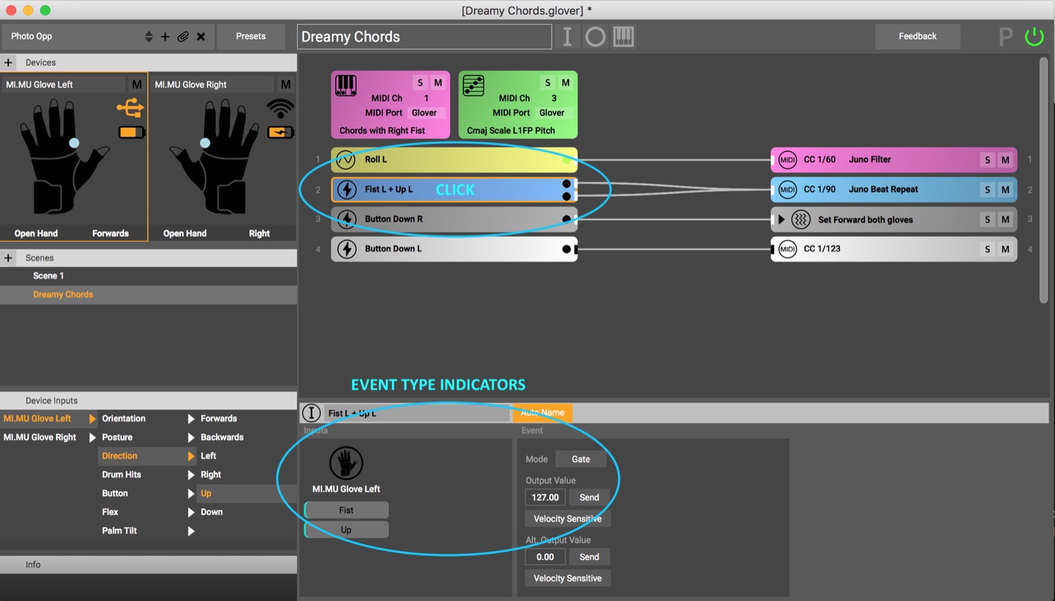 Individual event inputs are indicated by a blue color in the input box. Events can be simple triggers or accompanied by
values to allow for velocity sensitivity or other information. The available options for controlling information about
events that can be sent out via MIDI or OSC (see the Output Mappings section for guidance on how to select appropriate
output messages) are
Individual event inputs are indicated by a blue color in the input box. Events can be simple triggers or accompanied by
values to allow for velocity sensitivity or other information. The available options for controlling information about
events that can be sent out via MIDI or OSC (see the Output Mappings section for guidance on how to select appropriate
output messages) are
- Output Value
This is the value sent out by Glover when the defined input event (or combination of events) is detected.
Glover defaults this value to 127, which is equivalent to “on” or “all the way up” for most MIDI controls.
- Velocity Sensitive
For event inputs that also have velocity or other quantitative information attached to them, such as drum
hits, this button allows the user to send out the values that are coming from the input when it gets triggered.
This button does nothing if the input event does not contain velocity or other quantitative information.
- Detection Threshold
Also for event inputs that have quantitative information, this feature allows you to choose the minimum
value that needs to be detected before triggering the output. For example, it allows you to move freely without
accidentally triggering drums, and only trigger a drum hit when the hit is forcefully enough made.
- Mode
This option allows the event to function in three possible modes:
- Trigger
As a simple trigger, one output value is sent out whenever that Input is detected.
- Toggle
An additional second output now becomes available, as represented in the main mapping pane by another node
appearing on the right edge of the input, which can be sent to either the same or separate output(s). In the
Event window, a second output value appears that will be sent every other time the defined input combination is
detected. An example of how a toggle might be used is to define a specific posture to toggle something on and
off, so making a fist can alternate between starting and stopping a sound. Fist -> on (127), Fist -> off (0).
- Gate
Selecting this mode also causes a second output to be available. This mode is particularly useful if you
want to treat inputs as states - that is, when you want to send out information as long as a particular set of
inputs are happening, and then send out different information when they stop. For example, if you want a chord
to be triggered and for the sound to continue as long as you are making a fist, use this mode. Fist -> on (127),
Not Fist -> off (0).
- Send This button can be clicked when you want to quickly and easily test the output value without producing it with the actual device. Glover will send out a one-time output of the value you have entered so you can see or hear what effect that value produces, or so you can assign a new mapping.
Mapping Outputs
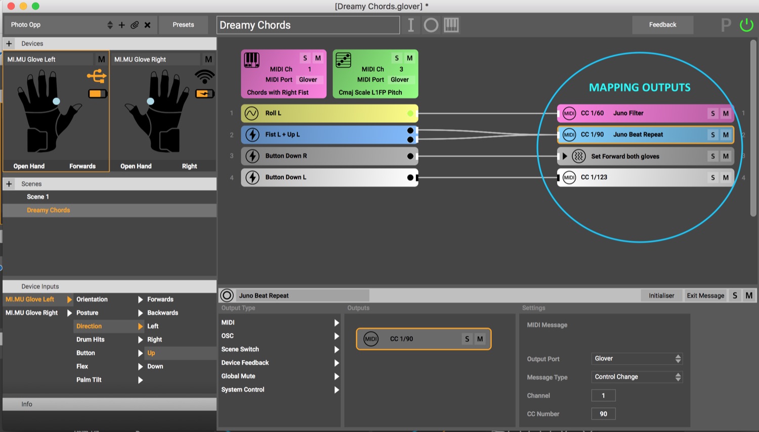
- Creating a new mapping Click on Mapping Output button (O) in the top toolbar. Click on the empty mapping output, then double click or select and drag across the type of output(s) you want to use to the ‘outputs’ panel which can be found at the bottom of the screen.
- Editing an existing mapping
Click on the output you wish to edit in the mapping window. Its properties will appear in the
inspector pane at the bottom of the window.
- Combining Mapping Outputs: Any number of Mapping Outputs of any type can be added to the “Outputs” window such that they all happen simultaneously with the same input. If multiple outputs are entered, you can see that indicated in the main mapping window in the upper right with a small triangle that can be opened to reveal all outputs in that mapping.
Types of Mapping Outputs:
1. MIDI:
This output format sends a MIDI message and is the most common message to use in combination with music software like Ableton Live. Below ‘Settings’ you choose what type of MIDI message to send.
a. Output Port
Select from the drop down the MIDI device that you would like to send from. Default is Glover.
b. Channel
There are 16 MIDI channels per port, enabling different types of messages or different instruments or different pieces of hardware to listen out for specific channels. For instance, one might choose always to send harmoniser messages to Channel 2, so that all MIDI mappings i nvolving the harmonizer use Channel 2. Only one MIDI channel can be selected per message, but duplicate messages can be sent on multiple channels.
c. Note On
There are 127 MIDI note numbers per MIDI channel. A good resource for correlating MIDI note number to note name and octave can be found here: https://newt.phys.unsw.edu.au/jw/notes.html. “Note on” sends a note number and a velocity value, often used to trigger a sound that does not need to be turned off.
d. Note Off
This can be used to turn off a note, and it also requires a MIDI note.
e. Note with length
This is equivalent to sending note on and then note off after a specified amount of time in between. The message also carries with it a velocity for the note on. If Note with Length is chosen, you can enter the note length (in milliseconds (ms)) manually in the field provided.
f. Control Change
There are 128 midi control change numbers with values 0-127 per channel. Control changes are used to provide continuous control of a parameter, such as volume or panning. For MIDI mapping to many continuous parameters in Ableton Live you will most often use a MIDI CC number.
g. Pitch Bend
Pitch bend is a specific MIDI control change message with values from 0-127 that communicates with the standard pitch bend controllers in many synthesizers and keyboard instruments, equivalent to the pitch bend wheel on a synthesizer.
h. Program Change
Program Change is another standard MIDI message with values 0-127 that can be used to change programs on a synthesizer or virtual instrument.
2. OSC This output format sends an Open Sound Control message and can be very useful for controlling other things than music. You can choose the Address Pattern, IP Address and Port in the setting of the mapping output.
a. Address pattern
Enter the OSC address here. Use spaces to seperate the different arguments to your message.
The value from the Mapping Input or Initaliser/Exit Message will be added as the last argument of the message by
default, but if you want that value to sit somewhere else in your message, you can use $ as a placeholder.
For example, '/MyAddress 1 $ 23. myargument' has 4 arguments. The
first is an integer, the second one is a placeholder for the Mapping Input value, the third is a float, the
fourth is a string
b. Destination Type
Choose whether you want to manually enter the IP Address & Port to use for this OSC message or you want to use a pre-set OSC Destinations that you can use globally throughout all your Glover projects. To set your OSC Destinations choose the OSC Destination option and click the pencil icon or go to the Edit menu and click OSC Destinations.
c. IP address
Enter the IP address of the device that will be receiving the OSC message
d. Port
Enter the port that the receiving device is listening on
e. Scene and Arrangement switching
OSC messages can be used to switch scenes and arrangements remotely. See our Glover remote control guidance for detailed guidance on navigating scenes and arrangements using OSC or MIDI from other applications or connected controllers.
3. Scene Switch
Use this output to navigate between scenes using a gesture or
other input. Switch
between scenes by setting a Scene Switch as an Output Format and choosing the
scene you want to switch to from the drop-down menu that appears.
NOTE: Any mapping output can be
designated as an initialiser or exit message to be executed automatically
upon entering or exiting a
scene. Initialiser and exit messages do not require any inputs to be connected
to them. More on
initialiser and exit messages can be found here. Tip on scene switching with
gestures: Make sure
not to map two scene switches in two scenes to the same input gesture. That is, if you make a
fist to go from Scene 1 to Scene 2, don’t program a fist to go from Scene 2 to Scene 3, or
Glover might take you straight through Scene 2 to Scene 3 before you can stop making a fist!
4. Device Feedback (MiMU Gloves specific)
Control the vibration motors, LED or Set Forward on the gloves by choosing Device Feedback as an Output Format. This can be very useful on stage to give yourself indications whether something has happened without having to look at the screen. For example, you can give yourself a buzz when you have set forwards or have a blue LED in Scene 1 and a pink LED in Scene 2.
a. Device
Choose which device you would like to affect.
b. Device Feedback types
i. LED Colour
Choose this to switch the glove’s LED to a static colour
ii. LED Gradient
Choose two colors and endpoint input values (min and max) that you would like to choose as endpoints that you then move between as the values of the chosen continuous movement inputs change.
iii. Vibration Motor
Sends a buzz to the motor on the back of the glove. A drop-down menu allows you to choose one, two, or three buzzes
iv. Set Forwards
This feedback allows you to define or re-define the “forward” direction, which then adjusts left, right, and backwards relative to the set forward position. This is extremely useful to map to a dedicated input, such as one of the buttons, in an always-active scene so that you can always adjust forward relative to your body if you’re moving around.
5. Global Mute
Mute all mapping outputs and instruments from Glover by mapping Global Mute as an Output Format. This can be useful when you are working in MIDI map mode in Ableton Live, but you don’t want to map anything from Glover. A value of 1 or higher turns Global Mute on and a value of 0 unmutes.
6. System Control
System control is a feature designed to expand in the future to control various aspects of the local computer outside of Glover, such as Keynote presentations or other OS functions. Currently, you can advance or back up a slide inside a Keynote presentation using a gestural mapping.
7. Speech
This output uses the text-to-speech feature of your computer's operating system to trigger spoken words. Type the desired words and select the voice options in the fields provided.
Output options
A very useful feature in glover is that glover outputs do not necessarily have to be triggered by gestural input - they can instead be triggered automatically upon entering or exiting scenes, which means you can do all sorts of magic instantaneously and on the downlow just by switching scenes!- Initialiser Messages Click this button if you would like to have this Output Message sent automatically upon entering into the current Scene. This means it requires no other input and you can have as many initialiser messages as you would like. Initialiser messages are executed before any other input-driven outputs, even if they appear after other mappings in the scene. When an Output Mapping is defined as an Initialiser message, it is required to add a value to be sent. For easy mapping during programming, assigning an output as an initialiser message allows you to send out a value directly by pressing the “send value” button.
- Exit Messages Click this button if you would like to have this Output Message sent automatically when leaving the current scene. Exit messages are executed immediately upon receiving a scene switch message. Exit messages also require values to be sent, as they also are not activated by inputs. For example, if you would like to re-set the reverb amount when you leave the scene, enter the value associated with the amount of reverb you would like to set. For easy mapping during programming, assigning an output as an exit message allows you to send out a value directly by pressing the “send value” button.
- Naming the Mapping Output Combination Symbols indicating the types of outputs comprising each mapping are added automatically, but if more than one output is listed, the default output box text is removed and you can create your own text for the mapping. For example, if an Output Mapping contains only one midi output, the display will automatically indicate that it’s a MIDI message, the type of MIDI message it is, and the note or cc number. You can then type additional identifying information in the box at the top of the inspector pane.Since people have different ways of thinking of output mappings, it may be useful to choose your own naming system for your outputs. It can be handy to name them in a way that indicates to you what they are doing, such as “Reverb control.”
- Solo When one or multiple Mapping Outputs or Instruments are soloed the Solo State Button turns yellow and indicates how many outputs are soloed. By clicking the Solo State button all soloed Mappings and Instruments will unsolo.
- Mute Individual Mapping Outputs can be muted using the Mute button on the right end of the Inspector Window toolbar.